There is an easy way to learn DirectX. Unfortunately, that easy way has a lot of limits to its capabilities, and even if it didn't, it is quite a hassle to use in large games. The easier way to program is, of course, harder to learn, and this lesson will cover that easier-to-program way, hopefully without making the learning part too hard.
In this lesson you will learn to draw a triangle on the screen. We will build this triangle by creating a series of vertices and having the Direct3D device draw them on the screen.
First we will cover the theory of how this all works, then we will go over the code itself and build the program.
If you went through Lesson 3 in any great detail, you will recall the definition of vertex: the location and properties of an exact point in 3D space. The location simply consists of three numerical values which represent the vertex's coordinates. The properties of the vertex are also defined using numerical values.
Direct3D uses a technology called a Flexible Vertex Format (or FVF). A vertex format is the layout of the data containing the location and properties of a vertex. A flexible vertex format would be a format of data that you can modify and set according to your needs. Let's take a look at how this works exactly.
A vertex is made of a struct, which contains the data pertinent to creating whatever 3D image it is made for. To display the image, we will copy all the information to the Video RAM and then order Direct3D to copy the data to the back buffer. However, what if we were forced to send all the data that could possibly be wanted for a vertex? This would happen.
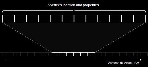
A Vertex Format Containing All Possible DataOf course, you may not see right away what the problem is here, but let's say we only needed two of these blocks of information. We could send it to the Video RAM much faster by doing it like this:
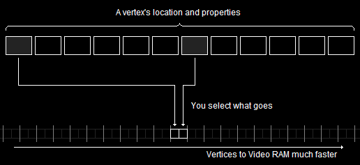
A Flexible Vertex Format Goes FasterThis is what happens when we use a flexible format. We select which information we want to use, and send just that, enabling us to send many more vertices between each frame.
In Direct3D, each vertex is made from a pre-set vertex format. As the title claims, this format is flexible, and is built using certain elements Direct3D provides. The elements are set using specific flags which, when logically ORed together, create a vertex definition, or a code that tells Direct3D the vertex format.
Let's take a look at how this is done. Let's say we want to include the location and the diffuse color of our vertices. We would build a code that looked like this:
#define CUSTOMFVF (D3DFVF_XYZRHW | D3DFVF_DIFFUSE)
Later, when we are working with the vertices, we will simply use CUSTOMFVF, rather than type out the entire FVF code each time. We'll see an example of this in a minute.
We can add all kinds of flags into this expression here. Following is a table of flags we will use throughout this tutorial, and a description of what they do (although don't go plugging them in randomly just yet).
| Flag | Description | Types Included |
|---|
| D3DFVF_XYZ | Indicates that the vertex format includes the X, Y and Z coordinates of an untransformed vertex. Untransformed means that the vertex has not yet been translated into screen coordinates. | float, float, float |
| D3DFVF_XYZRHW | Indicates that the vertex format includes the X, Y and Z coordinates as well as an additional RHW value of a transformed vertex. This means that the vertex is already in screen coordinates. The Z and the RHW are used when building software engines, which we will not get into. | float, float, float, float |
| D3DFVF_DIFFUSE | Indicates that the vertex format contains a 32-bit color code for a vertex, used for the color of diffuse lighting. | DWORD |
| D3DFVF_SPECULAR | Indicates that the vertex format contains a 32-bit color code for a vertex, used for the color of specular highlighting. | DWORD |
D3DFVF_TEX0
- through
D3DFVF_TEX8 | Indicates that the vertex format contains the coordinates for any textures that will be applied to a model. | float, float |
There are, of course, more things to put in, and they are all covered in the DirectX documentation. However, we will only be needing these flags for this tutorial.
Now we need to create the vertices using our new format. We don't use any new function or anything like that; we do it by building a simple struct containing the variables we included in the FVF code.
For instance, we used both the D3DFVF_XYZRHW and D3DFVF_DIFFUSE flags in the example above, and to go with it, we should build the following struct:
struct CUSTOMVERTEX
{
FLOAT x, y, z, rhw; // from the D3DFVF_XYZRHW flag
DWORD color; // from the D3DFVF_DIFFUSE flag
}
As you can see, the first four FLOATs are values represented by the D3DFVF_XYZRHW flag, while the DWORD is represented by the D3DFVF_DIFFUSE flag. If you look at the above table, you will find which variable types go with which FVF code flags.
Now let's build an actual vertex using our new CUSTOMVERTEX struct. We could do it like this:
CUSTOMVERTEX OurVertex = {320.0f, 50.0f, 1.0f, 1.0f, D3DCOLOR_XRGB(0, 0, 255)};
Of course, we could also make an array of vertices like this:
CUSTOMVERTEX OurVertices[] =
{
{320.0f, 50.0f, 1.0f, 1.0f, D3DCOLOR_XRGB(0, 0, 255),},
{520.0f, 400.0f, 1.0f, 1.0f, D3DCOLOR_XRGB(0, 255, 0),},
{120.0f, 400.0f, 1.0f, 1.0f, D3DCOLOR_XRGB(255, 0, 0),},
};
This results in a triangle, which we will see drawn on the screen shortly.
This is just one example of a Flexible Vertex Format. We will go over how to build more complex vertex formats later, but this one will do for now.
Now we have acomplished two things. First, we have built an FVF code. Second, we have constructed a triangle. Now we need to get that triangle ready for Direct3D to use. To do this, we create what is called a vertex buffer.
A vertex buffer is simply an interface that stores a section in memory (either Video RAM or system memory) to holds information about the vertices/models in your game. We create this interface by using the function CreateVertexBuffer(). The name is self-explanatory. It's parameters, however, are less merciful. Here is the prototype:
HRESULT CreateVertexBuffer(
UINT Length,
DWORD Usage,
DWORD FVF,
D3DPOOL Pool,
LPDIRECT3DVERTEXBUFFER9 ppVertexBuffer,
HANDLE* pSharedHandle);
Let's take these parameters up one at a time.
This parameter contains the size of the buffer that will be created. We get this number by multiplying the size of one vertex by the number of vertices that will be stored in the buffer. For example, a triangle contains three vertices, so the size of the triangle's buffer is: 3 * sizeof(CUSTOMVERTEX).
Sometimes there are special ways to use vertices which alter the DirectX handles the vertices. We will not get into these in any great detail in this tutorial. This parameter can contain flags indicating these special ways. As we won't be using any yet, we'll just set it to 0 for now.
This is the FVF code we constructed earlier. We just fill it in with CUSTOMFVF. If we went up to change the FVF code, this part would also change (hence the #define). This is what tells DirectX what format the vertices are in, so it is important that what you put here is accurate.
This parameter tells Direct3D where to create the vertex buffer and how. Following is a table that describes the possible entries for this parameter. For this tutorial, we will be using the flag D3DPOOL_MANAGED.
| Value | Description |
|---|
| D3DPOOL_DEFAULT | This flag indicates that the buffer should be created in the most appropriate memory for what settings and resources are available. This however, imposes some limits which are not always good for games. |
| D3DPOOL_MANAGED | This indicates that the buffer will be located in the video RAM. |
| D3DPOOL_SYSTEMMEM | This indicates that the buffer will be located in the system memory. Vertex buffers located here cannot usually be accessed by the Direct3D Device, but can be accessed by other, more advanced means. |
| D3DPOOL_SCRATCH | This also indicates the buffer will be located in system memory, however, there is no way for the video RAM to access this. This type is useful for storing graphics information that is not currently being used (but will be used later), such as graphics belonging to other maps a player hasn't reached yet, but might in the near future. |
If you can't decode that, it's the pointer to the vertex buffer interface we're making. We put the blank pointer in this parameter and the function simply fills it in for us.
The documentation says this parameter is, and I quote, "Reserved. Set this parameter to NULL". What this means I can't say for certain, but apparently Microsoft want us to set it to NULL. So be it. We'll set it to NULL.
And with all that in mind, let's take a look at how this function appears in our program:
LPDIRECT3DVERTEXBUFFER9 v_buffer;
d3ddev->CreateVertexBuffer(3*sizeof(CUSTOMVERTEX),
0,
CUSTOMFVF,
D3DPOOL_MANAGED,
&v_buffer,
NULL);
Now that you have created your vertex buffer, you need to load the vertices into it. You do this using a simple call memcpy(). However, before you can get access to the buffer, you need to lock it.
There are two reasons you need to lock the buffer. First, you need to tell Direct3D that you need complete control of the memory. In other words, it shouldn't be handled by any other process that might be going on. Second, you need to tell the video hardware not to move it around. There is no guarantee that the Video RAM will stay put. Locking tells the video hardware not to mess around with the memory while you are working with it.
To lock a buffer, you use the Lock() function, which has four parameters, but is actually quite simple:
HRESULT Lock(UINT OffsetToLock,
UINT SizeToLock,
VOID** ppbData,
DWORD Flags);
Let's go over these parameters.
If we only wanted to lock part of our vertex buffer, we would indicate that in these two parameters. The first one indicates how far into the buffer, in bytes, the lock should start. The second indicates how much should be locked, again in bytes. We want to lock the entire buffer, so we'll set both of these to 0.
Unless you are at least intermediate with C++ this will probably make no sense to you. Basically a void* is a pointer that points to no particular type of variable. For example, a double* points a double, whereas an int* points to an int. Each type of pointer has it's own format, and so it can't convert to another type without loss of data. A void* points to any of these, and can be converted without trouble.
Here we have a pointer to a void*. This pointer gets filled with the location of the memory to contain our vertices. The vertex buffer interface will take care of the details of this, but we need the pointer in the next step, so the Lock() function will fill this pointer with the proper address. Have a look at the example below to see how we fill this parameter.
This is an advanced parameter, and we won't get into it anywhere in this tutorial. They basically provide special ways to handle the locked memory. If you are truly interested, they can be researched in the DirectX documentation. For now, we will just set it to 0.
Let's fill this function out and see how it looks:
VOID* pVoid; // the void* we were talking about
v_buffer->Lock(0, 0, (void**)&pVoid, 0); // locks v_buffer, the buffer we made earlier
Next, we use a call to memcpy() to copy the vertices to the vertex buffer.
memcpy(pVoid, OurVertices, sizeof(OurVertices)); // copy vertices to the vertex buffer
Lastly, we have a very complicated function: Unlock(). This function has no parameters. What it does is tell Direct3D that we're all done with the memory, and it doesn't have to be locked anymore. It looks like this:
v_buffer->Unlock(); // unlock v_buffer
Because of the number of commands we've just learned, we're going to stick them all away into a single function of our own creation: init_graphics().
void init_graphics(void)
{
// create three vertices using the CUSTOMVERTEX struct built earlier
CUSTOMVERTEX vertices[] =
{
{ 320.0f, 50.0f, 0.5f, 1.0f, D3DCOLOR_XRGB(0, 0, 255), },
{ 520.0f, 400.0f, 0.5f, 1.0f, D3DCOLOR_XRGB(0, 255, 0), },
{ 120.0f, 400.0f, 0.5f, 1.0f, D3DCOLOR_XRGB(255, 0, 0), },
};
// create the vertex and store the pointer into v_buffer, which is created globally
d3ddev->CreateVertexBuffer(3*sizeof(CUSTOMVERTEX),
0,
CUSTOMFVF,
D3DPOOL_MANAGED,
&v_buffer,
NULL);
VOID* pVoid; // the void pointer
v_buffer->Lock(0, 0, (void**)&pVoid, 0); // lock the vertex buffer
memcpy(pVoid, vertices, sizeof(vertices)); // copy the vertices to the locked buffer
v_buffer->Unlock(); // unlock the vertex buffer
}
At this point I would suggest going over this section a couple times to make sure you thoroughly got it all. This is a rather key part of 3D programming, and we'll be using it and modifying it throughout the rest of the tutorial.
Now we actually get to have something on the screen! We have three very simple functions to talk about before this happens though. Each are called from the Direct3D Device interface. Let's take a look at each one.
The first of these functions is SetFVF(). SetFVF() is a function that tells Direct3D what FVF code we are using currently. We could, of course, have multiple FVF codes and use them in two different parts of the 3D scene. Before we draw anything, we need to tell Direct3D which one we are using. This function is written out like this:
d3ddev->SetFVF(CUSTOMFVF);
Next we have the function SetStreamSource(), which tells Direct3D which vertex buffer we are drawing from. This one has a couple parameters, so let's take a look at the prototype:
HRESULT SetStreamSource(UINT StreamNumber,
LPDIRECT3DVERTEXBUFFER9 pStreamData,
UINT OffsetInBytes,
UINT Stride);
The first parameter is the number of the stream source. We'll get into how this works later, but for now set it to 0, as we only have one vertex buffer.
The second parameter is the pointer to the vertex buffer we created earlier.
The third parameter is the number of bytes into the vertex buffer we should start from. This will usually be 0.
The last parameter is the size of each vertex. We fill this with: sizeof(CUSTOMVERTEX).
Let's take a look at the function as it is used:
d3ddev->SetStreamSource(0, v_buffer, 0, sizeof(CUSTOMVERTEX));
Now that we have told Direct3D what kind of vertices we are using and where to get them from, we tell it to draw the vertices we have built. This function draws the primitives in the selected vertex buffer to the screen. Here is the prototype:
HRESULT DrawPrimitive(D3DPRIMITIVETYPE PrimitiveType,
UINT StartVertex,
UINT PrimitiveCount);
The first parameter is the type of primitive that is used. These were covered in Lesson 3, but the codes used are here:
| Value | Description |
|---|
| D3DPT_POINTLIST | Shows a series of points. |
| D3DPT_LINELIST | Shows a series of separated lines. |
| D3DPT_LINESTRIP | Shows a series of connected lines. |
| D3DPT_TRIANGLELIST | Shows a series of separated triangles. |
| D3DPT_TRIANGLESTRIP | Shows a series of connected triangles. |
| D3DPT_TRIANGLEFAN | Shows a series of triangles with one shared corner. |
The second parameter is the number of the first vertex we will put on the screen. We could, if we wanted, start in the middle of the vertex buffer. However, we want the whole buffer drawn, so we will put 0 here.
The third and last parameter is the number of primitives we want to draw. If we draw a triangle, we put one here (there's only one triangle). If we were using points, we would put 3, as there are three points. Lines would also be 3.
Now let's take a look at the entire render_frame() function now that we have modified it.
// this is the function used to render a single frame
void render_frame(void)
{
d3ddev->Clear(0, NULL, D3DCLEAR_TARGET, D3DCOLOR_XRGB(0, 0, 0), 1.0f, 0);
d3ddev->BeginScene();
// select which vertex format we are using
d3ddev->SetFVF(CUSTOMFVF);
// select the vertex buffer to display
d3ddev->SetStreamSource(0, v_buffer, 0, sizeof(CUSTOMVERTEX));
// copy the vertex buffer to the back buffer
d3ddev->DrawPrimitive(D3DPT_TRIANGLELIST, 0, 1);
d3ddev->EndScene();
d3ddev->Present(NULL, NULL, NULL, NULL);
}
Before looking at the whole program, let's look at one last step that is required.
Just like the Direct3D Device and Direct3D itself, a vertex buffer must be released before our program closes.
// this is the function that cleans up Direct3D and COM
void cleanD3D(void)
{
v_buffer->Release(); // close and release the vertex buffer
d3ddev->Release(); // close and release the 3D device
d3d->Release(); // close and release Direct3D
}
Now let's take a look at the whole program to see what we have.
Ok, let's see what a triangle looks like. If you've never seen one, this will be an educational experience. If you have (please) you can see how one is made in Direct3D.
Anyway, let's examine the final DirectX code. The new parts covered in this lesson are in bold as usual.
[
Main.cpp]
// include the basic windows header files and the Direct3D header file
#include <windows.h>
#include <windowsx.h>
#include <d3d9.h>
// define the screen resolution
#define SCREEN_WIDTH 800
#define SCREEN_HEIGHT 600
// include the Direct3D Library file
#pragma comment (lib, "d3d9.lib")
// global declarations
LPDIRECT3D9 d3d; // the pointer to our Direct3D interface
LPDIRECT3DDEVICE9 d3ddev; // the pointer to the device class
LPDIRECT3DVERTEXBUFFER9 v_buffer = NULL; // the pointer to the vertex buffer
// function prototypes
void initD3D(HWND hWnd); // sets up and initializes Direct3D
void render_frame(void); // renders a single frame
void cleanD3D(void); // closes Direct3D and releases memory
void init_graphics(void); // 3D declarations
struct CUSTOMVERTEX {FLOAT X, Y, Z, RHW; DWORD COLOR;};
#define CUSTOMFVF (D3DFVF_XYZRHW | D3DFVF_DIFFUSE)
// the WindowProc function prototype
LRESULT CALLBACK WindowProc(HWND hWnd, UINT message, WPARAM wParam, LPARAM lParam);
// the entry point for any Windows program
int WINAPI WinMain(HINSTANCE hInstance,
HINSTANCE hPrevInstance,
LPSTR lpCmdLine,
int nCmdShow)
{
HWND hWnd;
WNDCLASSEX wc;
ZeroMemory(&wc, sizeof(WNDCLASSEX));
wc.cbSize = sizeof(WNDCLASSEX);
wc.style = CS_HREDRAW | CS_VREDRAW;
wc.lpfnWndProc = WindowProc;
wc.hInstance = hInstance;
wc.hCursor = LoadCursor(NULL, IDC_ARROW);
wc.lpszClassName = L"WindowClass";
RegisterClassEx(&wc);
hWnd = CreateWindowEx(NULL,
L"WindowClass",
L"Our Direct3D Program",
WS_OVERLAPPEDWINDOW,
0, 0,
SCREEN_WIDTH, SCREEN_HEIGHT,
NULL,
NULL,
hInstance,
NULL);
ShowWindow(hWnd, nCmdShow);
// set up and initialize Direct3D
initD3D(hWnd);
// enter the main loop:
MSG msg;
while(TRUE)
{
while(PeekMessage(&msg, NULL, 0, 0, PM_REMOVE))
{
TranslateMessage(&msg);
DispatchMessage(&msg);
}
if(msg.message == WM_QUIT)
break;
render_frame();
}
// clean up DirectX and COM
cleanD3D();
return msg.wParam;
}
// this is the main message handler for the program
LRESULT CALLBACK WindowProc(HWND hWnd, UINT message, WPARAM wParam, LPARAM lParam)
{
switch(message)
{
case WM_DESTROY:
{
PostQuitMessage(0);
return 0;
} break;
}
return DefWindowProc (hWnd, message, wParam, lParam);
}
// this function initializes and prepares Direct3D for use
void initD3D(HWND hWnd)
{
d3d = Direct3DCreate9(D3D_SDK_VERSION);
D3DPRESENT_PARAMETERS d3dpp;
ZeroMemory(&d3dpp, sizeof(d3dpp));
d3dpp.Windowed = TRUE;
d3dpp.SwapEffect = D3DSWAPEFFECT_DISCARD;
d3dpp.hDeviceWindow = hWnd;
d3dpp.BackBufferFormat = D3DFMT_X8R8G8B8;
d3dpp.BackBufferWidth = SCREEN_WIDTH;
d3dpp.BackBufferHeight = SCREEN_HEIGHT;
// create a device class using this information and the info from the d3dpp stuct
d3d->CreateDevice(D3DADAPTER_DEFAULT,
D3DDEVTYPE_HAL,
hWnd,
D3DCREATE_SOFTWARE_VERTEXPROCESSING,
&d3dpp,
&d3ddev);
init_graphics(); // call the function to initialize the triangle
}
// this is the function used to render a single frame
void render_frame(void)
{
d3ddev->Clear(0, NULL, D3DCLEAR_TARGET, D3DCOLOR_XRGB(0, 0, 0), 1.0f, 0);
d3ddev->BeginScene();
// select which vertex format we are using
d3ddev->SetFVF(CUSTOMFVF);
// select the vertex buffer to display
d3ddev->SetStreamSource(0, v_buffer, 0, sizeof(CUSTOMVERTEX));
// copy the vertex buffer to the back buffer
d3ddev->DrawPrimitive(D3DPT_TRIANGLELIST, 0, 1);
d3ddev->EndScene();
d3ddev->Present(NULL, NULL, NULL, NULL);
}
// this is the function that cleans up Direct3D and COM
void cleanD3D(void)
{
v_buffer->Release(); // close and release the vertex buffer
d3ddev->Release(); // close and release the 3D device
d3d->Release(); // close and release Direct3D
}
// this is the function that puts the 3D models into video RAM
void init_graphics(void)
{
// create the vertices using the CUSTOMVERTEX struct
CUSTOMVERTEX vertices[] =
{
{ 400.0f, 62.5f, 0.5f, 1.0f, D3DCOLOR_XRGB(0, 0, 255), },
{ 650.0f, 500.0f, 0.5f, 1.0f, D3DCOLOR_XRGB(0, 255, 0), },
{ 150.0f, 500.0f, 0.5f, 1.0f, D3DCOLOR_XRGB(255, 0, 0), },
};
// create a vertex buffer interface called v_buffer
d3ddev->CreateVertexBuffer(3*sizeof(CUSTOMVERTEX),
0,
CUSTOMFVF,
D3DPOOL_MANAGED,
&v_buffer,
NULL);
VOID* pVoid; // a void pointer
// lock v_buffer and load the vertices into it
v_buffer->Lock(0, 0, (void**)&pVoid, 0);
memcpy(pVoid, vertices, sizeof(vertices));
v_buffer->Unlock();
}
Go ahead and update your program and let's see what we get. If you run this, you should see the following on your screen:
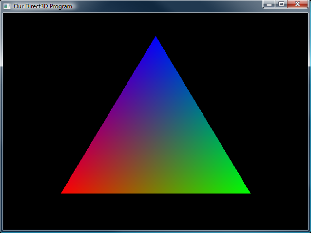
The Drawn Triangle Well done! You have made DirectX actually draw something. Of course, there is a lot more we can do, but let's start with what we have. I'd recommend doing the following short exercises before moving on, just so you get familiarity with the program.
1. Change the colors of the triangle.
2. Get the triangle to change shape during runtime.
3. Get the colors to fade from one point to the next.
Of course, you may be disappointed to find that this triangle is not 3D yet, but let's go on to the next lesson and make it 3D by rotating it, resizing it and moving it in a 3D world.
Next Lesson: Transforming Vertices
GO! GO! GO!
© 2006-2026 DirectXTutorial.com. All Rights Reserved.
Expand