If you have progressed through the tutorial this far, you are now ready to program in 3D. However, 3D programming is not like modeling clay, where you simply move the clay with your hands and everything looks perfect.
3D programming is strictly mathematical, and you must understand the concepts of 3D mathematics before you can effectively program with them. Don't worry, though. It's nothing complex. You won't need any more math than it takes to program in C++, so you should already be far enough along to be able to understand this.
This lesson is a theoretical lesson. We will cover the practice involved in the next lesson. In this lesson we will cover coordinate systems and how they apply to Direct3D and creating a 3D scene.
Without understanding of the basic math of 3D, 3D programming would be impossible. And I don't mean doing college algebra all over again, but just understanding the concepts of 3D coordinates, how they work and the various things which might get in your way.
Of course, before you understand 3D coordinate systems, you need to understand Cartesian Coordinates.
The Cartesian Coordinate System might be better recognized if called a 2D coordinate system. In other words, it is a system of locating an exact point on a flat surface.
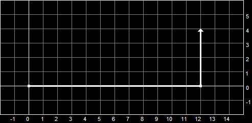
A point is defined as an exact position along an axis. If we wanted to know how far something has gone, we usually give an exact number, as in "Bob walked 12 meters". 12 meters is a distance along a single axis. We say that 0 is our starting point, and as Bob progresses, he moves farther and farther along this axis. This is a 1D coordinate system.
1D Coordinate SystemWhen we look at this scenario from the side, as in the picture, we can see that as Bob continues walking toward the right of the screen, his distance travelled increases away from 0. We will call this '0' the origin, as it is where he started from. On the other side of the origin, we would have negative values instead of positive values.
However, what if he were then to turn 90 degrees and walk in a different direction? Truthfully, Bob would then be walking along a second axis, and we would diagram his path like this:
The Cartesian Coordinate SystemNow that we have more than one axis, we give ourselves a way to identify them. The horizontal axis, along which Bob walked 12 meters, we will call the x-axis. The vertical axis we will call the y-axis.
Of course, this new axis, like the horizontal axis, also has an origin. It is the point where Bob stopped walking sideways and started walking up. Notice that the y-axis origin is also given the value of 0, and increases the farther Bob walks. (go Bob go...)
So now we have two axes (the x-axis and the y-axis), and each have their origins. Well, this is what forms our Cartesian Coordinate System. We can now locate any point along this surface (probably the ground in Bob's case). We can state Bob's exact position by saying how far he is off of each axis' origin, so we could say he is at (x, y) or (12, 4), 12 being his position on the x-axis and 4 being his position on the y-axis.
These two numbers are called coordinates, and are used to show how far an exact point is from the origin (or the '0' point on both axes).
Actually, the 3D Coordinate System is merely an extention to what we have been discussing. If we took Cartesian Coordinates and added a third axis (a z-axis) running perpendicular to both the x and y axes, we would have 3D coordinates. This is illustrated here.
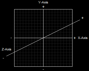
The 3D Coordinate SystemLike Cartesian Coordinates, 3D coordinates can be both positive and negative, depending on which direction the point is. However, instead of being written like Cartesian Coordinates, 3D coordinates are written with three numbers, like this: (x, y, z) or (12, 4, 15). This would indicate that Bob was somehow fifteen meters in the air. It could also be written (12, 4, -15). Perhaps this means he's lost in a dungeon somewhere.
Now let's cover how 3D coordinates are applied to games and game programming. If a point in a 3D coordinate system represents a position in space, then we can form an array of exact positions which will eventually become a 3D model. Of course, setting so many points would take up a lot of space in memory, so an easier and faster way has been employed. This method is set up using triangles.
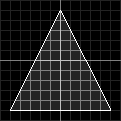
Triangles, of course, are a very useful shape in just about any mathematical area. They can be formed to measure circles, they can be used to strengthen buildings, and they can be used to create 3D images. The reason we would want to use triangles is because triangles can be positioned to form just about any shape imaginable, as shown in these images:
Models Made From TrianglesBecause of the useful nature of triangles when creating 3D models, Direct3D is designed solely around triangles and combining triangles to make shapes. To build a triangle, we use something called vertices.
Vertices is plural for vertex. A vertex is defined as an exact point in 3D space. It is defined by three values, x, y and z. In Direct3D, we add to that a little. We also include various properties of this point. And so we extend the definition to mean "the location and properties of an exact point in 3D space".
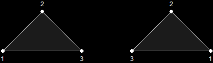
A triangle is made up of three vertices, each defined in your program in clockwise order. When coded, these three vertices form a flat surface, which can then be rotated, textured, positioned and modified as needed.
A Triangle Built From VerticesThe triangle shown in the above image is created by three points:
x = 0, y = 5, z = 1
x = 5, y = -5, z = 1
x = -5, y = -5, z = 1
You will notice that all the above vertices have a z-value of 1. This is because we aren't talking about a 3D object; we are talking about a triangle, which is a 2D object. We could change the z-values, but it would make no essential difference.
To make actual 3D objects, we will need to combine triangles. You can see how triangles are combined in the above diagram. To take a simple example, the cube is simply two triangles placed together to create one side. Each side is made up of identical triangles combined the same way.
However, defining the 3D coordinates of every triangle in your game multiple times is more than just tedious. It's ridiculously complex! There's just no need to get that involved (and you'll see what I mean in the next lesson).
Instead of defining each and every corner of every triangle in the game, all you need to do is create a list of vertices, which contain the coordinates and information of each vertex, as well as what order they go in.
A primitive is a single element in a 3D environment, be it a triangle, a line, a dot, or whatever. Following is a list of ways primitives can be combined to create 3D objects.
1. Point Lists
2. Line Lists
3. Line Strips
4. Triangle Lists
5. Triangle Strips
6. Triangle Fans
A Point List is a list of vertices that are shown as individual points on the screen. These can be useful for rendering 3D starfields, creating dotted lines, displaying locations on minimaps and so on. This diagram illustrates how a Point List is shown on the screen (without the labels, of course).
A Point List (6 Primitives)A Line List is a list of vertices that create separate line segments between each odd-numbered vertex and the next vertex. These can be used for a variety of effects, including 3D grids, heavy rain, waypoint lines, and so on. This diagram illustrates how a Line List is shown on the screen (this is the same set of vertices as before).
A Line List (3 Primitives)A Line Strip is similar to a line list, but differs in that all vertices in such a list are connected by line segments. This is useful for creating many wire-frame images such as wire-frame terrain, blades of grass, and other non-model-based objects. It is also very useful in debugging programs. This diagram illustrates how a Line Strip is shown on the screen.
A Line Strip (5 Primitives)A Triangle List is a list of vertices where every group of three vertices is used to make a single, separate triangle. This can be used in a variety of effects, such as force-fields, explosions, objects being pieced together, etc. This diagram illustrates how a Triangle List is shown on the screen.
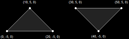
A Line List (2 Primitives)A Triangle Strip is a list of vertices that creates a series of triangles connected to one another. This is the most-used method when dealing with 3D graphics. These are mostly used to create the 3D models for your game. This diagram illustrates how a Triangle Strip is shown on the screen. Notice that the first three vertices create a single triangle, and each vertex thereafter creates an additional triangle based on the previous two.
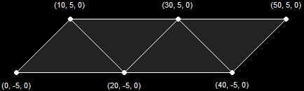
A Triangle Strip (4 Primitives)A Triangle Fan is similar to a triangle strip, with the exception that all the triangles share a single vertex. This is illustrated in this diagram:
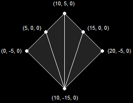
A Triangle Fan (4 Primitives)There is a slight quirk in drawing primitives where only one side of the primitive is shown. It is possible to show both sides, but usually a model is completely enclosed, and you cannot see the inside of it. If the model is completely enclosed, only one side of each triangle need be drawn. After all, drawing both sides of a primitive would take twice as much time. You will see an example of this in the next couple of lessons.
A triangle primitive is only drawn when its vertices are given in a clockwise order. If you flip it around, it becomes counter-clockwise, and is therefore not shown.
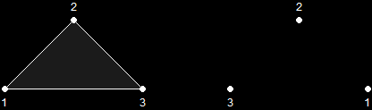
Primitive Only Visible When Drawn ClockwiseThere is an easy way (though tedious when you get into larger games) to show both sides of a primitive, which is to show the primitive twice, giving one primitive clockwise and the other counter-clockwise.
Primitive Visible When Drawn Either Way Color is a rather simple part of 3D programming. However, even if you are very familiar with color spectrums and the physics of light, it would be good to know that Direct3D does not follow the laws of this universe exactly. To do so would be a nightmare on graphics hardware and the CPU. It's just too much, and so we'll just leave graphics like that to the Matrix and make our own laws that we can cope with.
Light, of course, is a wavelength of particles that allows you to see and differentiate between various objects around you. Direct3D mimicks this with various mathematical algorithms performed by the graphics hardware. The image is then displayed on the screen appearing well lit. In this section we'll cover the mechanics of how Direct3D mimicks the light we see in nature.
In the younger years of your education you may have learned the primary colors to be red, blue and yellow. This isn't actually the case. The colors are actually magenta, cyan and yellow. And why this useless technical detail? To understand this, you must understand the concept of subtractive and additive color.
The difference between these two types of color have to do with whether or not the color refers to the color of light or the color of an object. Subtractive color is the color of an object, and has the primary colors magenta, cyan and yellow. Additive color is the color of light, and has the primary colors red, green and blue.
In a beam of light, the more primary colors you add the closer you get to white. The colors add together to make white, and thus it is called additive color.

Additive Colors Add Up to WhiteAbove you can see the primary colors of light combine to make white. However, if you look, you will also see that when you combine two of the colors, you get one of the primary subtractive colors (magenta, cyan or yellow). If we take a look at these subtractive colors, we'll see why this is.
Subtractive colors are essentially the opposite of additive colors. They consist of the light that is not reflected off the surface of an object. For example, a red object illuminated by a white light only reflects red light and absorbs green and blue light. If you look at the above image, you will see that green and blue combined make cyan, and so cyan was subtracted from the white light, resulting in red.

Subtractive Colors Subtract Out to BlackIn graphics programming, you will always use the additive colors (red, green and blue), because monitors consist of light. However, when building a 3D engine, it is good to understand what makes objects look the colors they do.
By the way, this is why you find magenta, cyan and yellow in printers, and red, green and blue on screens.
If you want to really get into color, then following is an article which gives a thorough rundown of color and the physics of light. If you're thinking of the future and DirectX 10's nextgen games, I'd seriously recommend knowing your color well. There's much more to it than you'd think at first, and it makes a big difference in making a great game engine.
Anyway, here's the article.
Alpha coloring is an additional element to the red-green-blue color of light. When you include some Alpha into your color, the graphic appears semi-transparent, allowing you to see through the object somewhat. This is useful for creating a semi-transparent display for your game, having units cloak (but still be seen somewhat by allies), and numerous other things. I'm sure your imagination can run rampant for some time on this one.
Color in Direct3D comes in the form of a 32-bit variable which stores all the information about the color. This includes the primary colors (refered to as RGB for Red, Green and Blue) and the amount of Alpha in the color. Each of these are refered to as channels, and each take up 8-bits, as showed here:
Bit Layout of ColorFollowing is the code that defines the above colors:
DWORD Color_A = 0xff00ff00;
DWORD Color_B = 0x88ff00cc;
There are also two functions we can use to build these colors for us, in case we need to plug variables into these values.
DWORD Color_A = D3DCOLOR_XRGB(0, 255, 0);
DWORD Color_B = D3DCOLOR_ARGB(136, 255, 0, 204);
The function D3DCOLOR_ARGB() returns a DWORD filled with the proper values for the color you are building. If you don't want to bother with Alpha, then you can use the D3DCOLOR_XRGB() which does the exact same thing, but automatically fills the Alpha channel with 255.
If you want to see an example of this, check out the example from Lesson 1 and 2, which clear the screen using the D3DCOLOR_XRGB() function.
I'm not going to cover everything about light here. I'll save that for a later lesson. For now, I just want to cover the basic light equasion, as you will have to understand parts of it before you actually add lighting into your program.
Light in nature is a very complicated subject mathematically speaking. When the sun shines, almost everything is lit by it, even though the sun is not shining on a lot of what can be seen. This is because light bounces around an area thousands of times, hitting just about everything, whether the sun shines there or not. To further add to this equation, as the sunlight travels through space, some of it is reflected off dust particles, which scatter the light in a completely uncalculatable pattern. Even if a computer could calculate all this, it could not run real-time.
Direct3D uses a system to mimick the light of a real-life environment. To do this, it breaks light down into three types of light that, when combined, closely approximate actual light. These three types of light are Diffuse Light, Ambient Light and Specular Light.
Diffuse Light is light that shines upon an object indirectly. This sphere is lit by diffuse lighting alone.
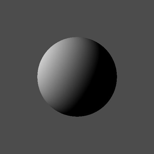
Diffuse LightLater, you will learn about sources of light. This sphere is lit by one source, coming off from the left somewhere. The further the sphere curves away from the light, the less that portion is lit by the source.
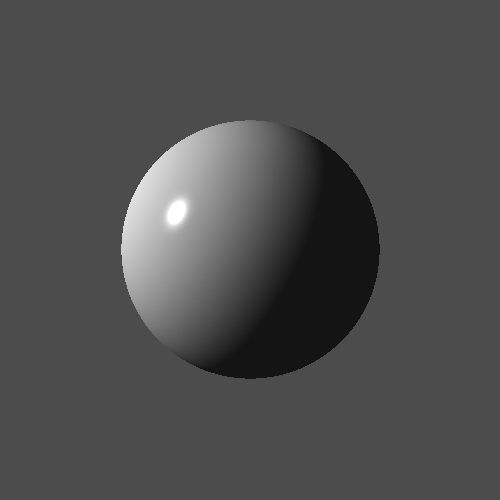
Ambient Light is light that is considered to be everywhere. Unlike the diffuse light, it has no source, and if used alone appears a circle (because all parts are lit equally under this lighting). This sphere is the same sphere as last time, but this time has ambient lighting included to fill in the dark, unlit parts.

Diffuse and Ambient LightingThis is sometimes refered to as Specular Highlight, because it highlights an object with a reflective color. This sphere is lit with Diffuse and Ambient Light, and has a Specular Highlight added to make it look more real.
Diffuse, Ambient and Specular Lighting By now you should understand the basic underlying concepts of the third dimension, and how it is applied to game programming. Now let's go on and put all this theory into practice. In the next lesson, you will take what you know from this lesson and build a basic triangle.
Next Lesson: Drawing a Triangle
GO! GO! GO!
© 2006-2026 DirectXTutorial.com. All Rights Reserved.
Expand