In the last lesson you built a simple, flat triangle lit with simple diffuse lighting. This triangle was not 3D, it was flat. If you managed to change it, you found it was a 2D triangle drawn in screen coordinates. The triangle you made was pre-transformed, meaning you took no action to convert it from 3D coordinates to screen coordinates, but just gave Direct3D the screen coordinates.
In this lesson, you will learn to transform vertices, or convert them from 3D coordinates to screen coordinates. You will also learn to position the 3D camera, set the 3D "lens", and put your triangle into a 3D world with other 3D objects in it.
Note: If you get confused or overwhelmed in this lesson, make sure you do the exercises listed at the end. Learning this topic is a bit like learning pointers for the first time: you don't get it until you get it, and that's all there is to it. To "get" how to do this, you just need to do it, so I recommend doing these exercises so you can "get it" before you tackle the rest of Direct3D.
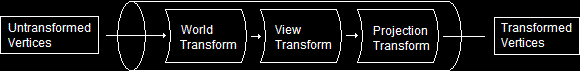
Before we get into the actual transformation code, let's take a look at everything that happens to translate something from 3D coordinates to a flat image. There is a sequence of actions which must occur before an object appears on the screen properly. This sequence of actions is known as the Geometry Pipeline. It is called a pipeline because vertices are put through each step one at a time, and at each step along the "pipe", the vertex is rendered into its flat image form.
When a model first starts out, it is generally centered on the origin, meaning the center of the object is at (0, 0, 0). This also means that all the objects in your game will be in the exact center of the world, all piled up on top of each other, which doesn't make a very excellent game. The first step is to sort out the new positions of all the models in relation to each other. This is called World Transformation.
Once all the objects in the world have been sorted out and the vertices' positions have been altered to represent world coordinates, then we have to change the entire coordinate system to create a virtual camera. What this means is that we have to change the direction of each axis, in order to position everything in the most efficient way for the video card. This process is known as View Transformation.
After the coordinate system has been rearanged, then it is time to convert all the 3D models into 2D images. In this step, the 3D coordinates are converted into screen coordinates. This process is known as Projection Transformation.
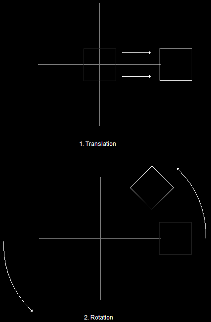
The Geometry PipelineWorld Transformation, in essence, changes coordinates from model space to world space. In other words, it places a model in a world at an exact point defined by coordinates. Following is an overhead demonstration of how this works:
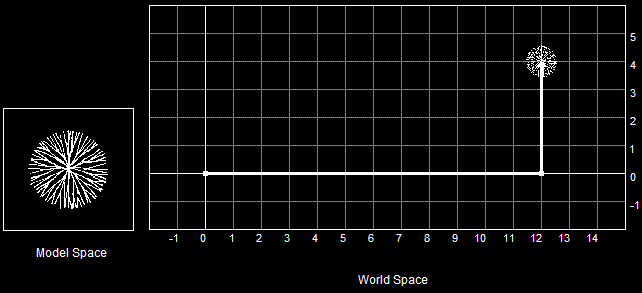
Model TranslationThis is known as translation. Translation refers to the movement of a vertex along a coordinate system axis. For example, the above diagram shows movement of a tree along the x and y axes. Of course, we could also translate the tree along the z-axis, but our ground here is flat, and having trees floating ten feet high just outside the local village tends to scare the tourists away (not to mention the players).
Of course, being able to move an object into world space is always useful, but it can get rather limiting if your model is always facing the same direction. A spaceship that can only face East is rather dull and does not elicit much thrill or adrenaline (or so I find).
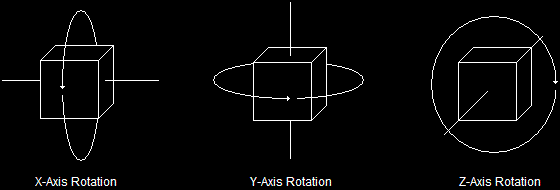
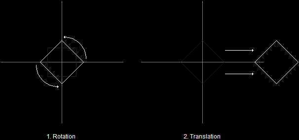
And so another part of World Transformation is rotation. Rotation is the process of spinning 3D objects along an axis. Like translation, it can be done along multiple axes simultaneously, allowing you to position your model as desired.
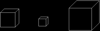
Model RotationAnother important part of World Transformation is scaling. Scaling is the action of making a 3D object larger or smaller. When an object is scaled, each vertex in the object is multiplied by a given number. These numbers can be different for each axis, resulting in various stretching effects.
Model ScalingView transformation is a process which sets up the 3D coordinate system to point in the proper direction. What this means is that the directions of each axis are going to change to point in different directions. Let me explain:
Direct3D uses the concept of a virtual camera. This camera has an exact position and points at an exact vector. When world transformation is done, the 3D axes have no alignment to how the scene will be viewed.
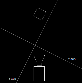
3D Axes Unaligned With CameraIn order for Direct3D and the video card to quickly process the 3D scene, the 3D axes must align with the camera. Specifically, the origin is repositioned to where the camera is, and the z-axis points directly down the line of sight.
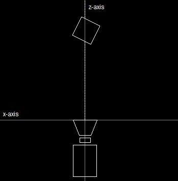
3D Axes Aligned With CameraNotice that while the axes changed, the box and the camera stayed still. Of course, if the 3D axes change, the 3D coordinates of the box must also change if this is to happen. View transformation is the process which quickly and cleanly calculates this change.
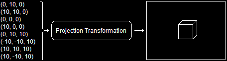
If view transformation can be thought of as a camera, then this step can be thought of as a lens. Once view transformation is completed, we have to change the 3D scene into one big 2D image so it can be drawn on the screen. The process that does this is called projection transformation. It is simply the converting of 3D coordinates to screen coordinates.
Projection TransformationNow that we have covered a theoretical approach of the three different transformations that occur, let's take a look at how to implement them in practice.
The last section described how to change vertices from untransformed vertices to transformed vertices, or in other words, how to change 3D models to 2D images.
If you have been following through this entire tutorial, you will have noticed that we have been dealing only in 2D coordinates up until this point. You defined you custom FVF like this:
struct CUSTOMVERTEX {FLOAT X, Y, Z, RHW; DWORD COLOR;};
#define CUSTOMFVF (D3DFVF_XYZRHW | D3DFVF_DIFFUSE)
This code describes pre-transformed vertices, meaning they did not have to go through the 3D pipeline (because they were already given in 2D form).
For vertices to be in 3D form, they are described like this:
struct CUSTOMVERTEX {FLOAT X, Y, Z; DWORD COLOR;};
#define CUSTOMFVF (D3DFVF_XYZ | D3DFVF_DIFFUSE)
All we really did here was take out the RHW, but that was enough. If you make this modification and run the program, you will find that nothing will show up. The reason? You are trying to draw 3D coordinates on a flat screen without putting those coordinates through the pipeline. Let's find out how to do this.
A matrix is a mathematical term which describes a two-dimensional array of numbers. Here is an example of a 4x4 matrix with the values 1 through 16:
In 3D programming, a matrix is used to represent information used during transformations. We'll go over how they are used in a minute, but for now, let's focus on the matrix itself.
A matrix can be defined in C++ like this:
float TheMatrix [4][4] =
{
1.0f, 0.0f, 0.0f, 0.0f,
0.0f, 1.0f, 0.0f, 0.0f,
0.0f, 0.0f, 1.0f, 0.0f,
0.0f, 0.0f, 0.0f, 1.0f
};
When using Direct3D transformations, you use matrices to multiply values together in order to bring about certain results. Before you set the values inside a matrix, you need to set the matrix to its default. This default is called the identity matrix. The above example code shows the values contained in an identity matrix.
Using a 2 dimensional array of float values can be exhaustingly tedious. To bypass this, Direct3D uses a struct and a series of functions which can be used to greatly simplify matrices. We will cover the functions throughout this lesson, but we'll start with the struct here. Here is the struct's defintion:
typedef struct _D3DMATRIX {
union {
struct {
float _11, _12, _13, _14;
float _21, _22, _23, _24;
float _31, _32, _33, _34;
float _41, _42, _43, _44;
};
float m[4][4];
}
} D3DMATRIX;
Of course, this doesn't handle the tedious intializing, so we'll use a simple Direct3D function to handle this for us. This function is called D3DXMatrixIdentity(). It's prototype is:
D3DXMATRIX* D3DXMatrixIdentity(D3DXMATRIX* pOut);
This is a simple function. Its one parameter is a pointer to the matrix we want to set up as the default identity matrix.
For convenience, it also uses the exact same value as a return value, so it can be used as a function parameter as well.
You are probably wondering what matrices are for. A Direct3D matrix is used to store data required by a transformation. It is stored in such a way that all that needs to be done is some simple multiplication, and the transformation just happens. We could go into the exact mathematics of this for at least five or six lessons, but fortunately there are functions to take care of it all for us.
As you recall, creating a world space (world transformation) consists of the translation (moving), rotation and scaling of 3D models into world space. The vertices in each model are multiplied by a matrix to perform each of these.
To do this, our first step will be to create the matrices, and our second step will be to tell Direct3D that we want to use them, and in what order (what order of multiplication, that is).
The following is the code required to set up a simple translation. It can be run between the SetStreamSource() function and the DrawPrimitive() function.
D3DXMATRIX matTranslate; // a matrix to store the translation information
// build a matrix to move the model 12 units along the x-axis and 4 units along the y-axis
// store it to matTranslate
D3DXMatrixTranslation(&matTranslate, 12.0f, 4.0f, 0.0f);
// tell Direct3D about our matrix
d3ddev->SetTransform(D3DTS_WORLD, &matTranslate);
Lets go over each one of these.
We covered this one in the last section. This creates a matrix. We will call it matTranslate to keep it from getting confused with other matrices later on.
This function is used to initialize the matrix with the proper values used for translation. The first parameter is the address of the matrix, and the following three parameters are float values, corresponding to the x-axis, y-axis and z-axis movement.
This function has a new parameter in it, but the second parameter is obvious (the address of the matrix we just built).
This function tells Direct3D that the matrix we built should be used for any vertices processed. That means that later, when we run the DrawPrimitive() function, our matrix will be used to move the vertices around in the world space.
The first parameter is a flag that tells Direct3D what kind of matrix this is (there are more kinds). The kind we are building is a World Transform matrix, and the flag that applies is D3DTS_WORLD. The other kinds we could put (but we won't yet) are the D3DTS_VIEW, which specifies a View Transform matrix, and the D3DTS_PROJECTION, which specifies a Projection Transform matrix. We'll go over this in more detail later. For now, set this value to D3DTS_WORLD.
Rotation is done in almost exactly the same way, although there is one slight complication. Rotation can occur in three different directions (x-axis, y-axis and z-axis). Therefore, there is a function to set up a matrix for each type of rotation. However, let's start simple and use one at a time.
D3DXMATRIX matRotateX; // a matrix to store the rotation information
// build a matrix to rotate the model 3.14 radians
D3DXMatrixRotationX(&matRotateX, 3.14f);
// tell Direct3D about our matrix
d3ddev->SetTransform(D3DTS_WORLD, &matRotateX);
Much of this is similar, but we'll go over it again briefly.
This is the name of our matrix. We are only going to rotate on the x-axis this time, so we'll label the matrix as such for clarity.
This function builds a matrix that indicates an x-axis rotation. The first parameter gives the address of the matrix to be built, and the second parameter gives the number of radians the model should be rotated (as a float value).
Of course, similar functions also exist for the y-axis and z-axis. All you have to do is replace the 'X' with a 'Y' or a 'Z', and there you go (the parameters are the same). We'll get into how to do multiple-axis rotations later in the lesson. For now, you see how one rotation is done.
Note that you can also use degrees instead of radians by using the D3DXToRadian() function. It's one parameter is a float value indicating the number of degrees, and the return value is a radian. So you could change the rotation matrix function above into this:
D3DXMatrixRotationX(&matRotateX, D3DXToRadian(180.0f));
If you had done this instead, it would have had almost exactly the same result. (Almost exactly, because 180 degrees is not exactly 3.14 radians, but rather, 3.141592653589793238462643383279502884197169399375105820974944592 radians, and even that isn't perfect. If you really want the full value of pi, go here, otherwise, let's just stick with degrees, yea?)
Trivial data aside, let's move on.
This function operates exactly the same as in the translation. It sets the entire world transformation to be based on the matRotateX matrix we built.
Scaling is done like translation and rotation and has its own function for initializing the matrix before using it.
D3DXMATRIX matScale; // a matrix to store the scaling information
// build a matrix to double the size of the model
// store it to matScale
D3DXMatrixScaling(&matScale, 2.0f, 2.0f, 2.0f);
// tell Direct3D about our matrix
d3ddev->SetTransform(D3DTS_WORLD, &matScale);
The first and last commands are the same, but let's go over this new function:
This function sets the matrix to scale the vertices to a specific size. The first parameter is the same as before, a pointer to the matrix to be initialized. The next three are float values which represent how much the vertices should be scaled by.
In this example, all the vertices calculated get multiplied by 2.0f. If a vertex's coordinates started out as (4, 4, 4), they would be (8, 8, 8) when drawn.
Of course, you can put different values in each of those three parameters, getting various results (stretching the model). You can also put negative values (to reverse the coordinates) and decimals (to make the model smaller).
So far we have gone over how to do one type of calculation at a time. The problem is, if we wanted to do both, we would only get to use the one we did later. The SetTransform() function sets one matrix as the thing to use with the world transformation. If you try to set another matrix later, Direct3D only uses the second one, and completely ignores the first one.
We can solve this problem by multiplying matrices together to form new matrices. It so happens that if you multiply a matrix with another matrix, the result will contain the effects of both matrices.
For example, if we had a matrix that rotated and a matrix that scaled, and we multiplied these two matrices together, the result would be a matrix that rotated and scaled! Let's see how this is done:
D3DXMATRIX matRotateX; // a matrix to store the rotation information
D3DXMATRIX matScale; // a matrix to store the scaling information
D3DXMatrixScaling(&matScale, 2.0f, 2.0f, 2.0f); // double the size of the model
D3DXMatrixRotationX(&matRotateX, D3DXToRadian(90.0f)); // rotate the model 90 degrees
// set the world transform to the two matrices multiplied together
d3ddev->SetTransform(D3DTS_WORLD, &(matRotateX * matScale));
And there you have it! We have now set the world transform to A) rotate all models by 90 degrees, and B) to double the size of all models.
Let's take another example, just for the sake of repetition:
D3DXMATRIX matRotateX;
D3DXMATRIX matRotateY;
D3DXMATRIX matRotateZ;
D3DXMATRIX matScale;
D3DXMATRIX matTranslate;
D3DXMatrixRotationX(&matRotateX, D3DXToRadian(50.0f));
D3DXMatrixRotationY(&matRotateY, D3DXToRadian(50.0f));
D3DXMatrixRotationZ(&matRotateZ, D3DXToRadian(50.0f));
D3DXMatrixScaling(&matScale, 5.0f, 1.0f, 1.0f);
D3DXMatrixTranslation(&matTranslate, 40.0f, 12.0f, 0.0f);
d3ddev->SetTransform(D3DTS_WORLD,
&(matRotateX * matRotateY * matRotateZ * matScale * matTranslate));
What this one does is rotate the model along the x-axis 50 degrees, then the y-axis, then the z-axis. Then it stretches the model five times its usual size along the x-axis. Last, it translates the model to its new position: (40, 12, 0).
Next, let's look at a slightly altered version of our SetTransform() function. What if we had done this:
d3ddev->SetTransform(D3DTS_WORLD,
&(matTranslate * matRotateX * matRotateY * matRotateZ * matScale));
At first, this seems to be a very innocent change. All we did was multiply the &matTranslate matrix before all the others, right? Mathematical order of operations tells us the answer should be the same, right?
No, unfortunately not. Observe:
Rotating Before TranslatingHowever, if you rotate a model after you translate it, you get this instead:
Rotating After TranslatingThis effect can be useful in some cases, but it is worth mentioning because you don't always want it (and it can be frustrating if you don't know what is causing it).
That about wraps it up for World Transformation. There are additional things that can be learned, but it is probably best that they come to you with experience, in addition to long hours of exploring the documentation.
If at this point you are feeling a bit overwhelmed by all this, I would suggest going back up to where it was easy and go over it again and again until you get it. This lesson is covering a very important part of 3D programming, and I would hate for you to miss it.
Setting the view transformation can be considered to be similar to setting up a virtual camera. All a programmer does with this is feed the camera position, direction and rotation into a single matrix. There is no need to multiply matrices here like there was in world transformation. There is only one matrix, and one function to build that matrix.
Let's say we want to have the player view an object located at the world's origin (0, 0, 0). We want the player to be viewing the object from the coordinates (100, 100, 100). To do this we need to build a matrix containing this data. We build this matrix using a function called D3DXMatrixLookAtLH(). Here is the prototype:
D3DXMATRIX* D3DXMATRIXLookAtLH(D3DXMATRIX* pOut,
CONST D3DXVECTOR3* pEye,
CONST D3DXVECTOR3* pAt,
CONST D3DXVECTOR3* pUp);
Let's go over these, because they are not all self-explanatory.
First, we will talk about this new type, CONST D3DXVECTOR3*. D3DXVECTOR3 is a very simple struct which simply holds three values:
typedef struct D3DXVECTOR3
{
FLOAT x; // contains an x-axis coordinate
FLOAT y; // contayns a y-axis coordinate
FLOAT z; // containz a z-axis coordinate
} D3DXVECTOR3, *LPD3DXVECTOR3; // go speling
Now that we know all the syntax of the D3DXMATRIXLookAtLH() function, let's define each parameter:
We know this one. It is the pointer to the matrix we are going to fill.
This parameter is a pointer to a vector which contains the exact position of the camera. Considering our example above, we want to fill this struct with (100, 100, 100).
This vector contains the exact location the camera should look at. Our example is looking at (0, 0, 0), so we will fill this struct with those values.
This vector contains the direction of "up" for the camera. In other words, what direction will the top of the screen be. Usually, game programmers use the y-axis as the "up" direction. To set the camera this way, you simply need to fill this struct with (0, 1, 0), or 1.0f on the y-axis and 0.0f on the other two.
Ok, let's take a look at how this appears in real code:
D3DXMATRIX matView; // the view transform matrix
D3DXMatrixLookAtLH(&matView,
&D3DXVECTOR3 (100.0f, 100.0f, 100.0f), // the camera position
&D3DXVECTOR3 (0.0f, 0.0f, 0.0f), // the look-at position
&D3DXVECTOR3 (0.0f, 1.0f, 0.0f)); // the up direction
d3ddev->SetTransform(D3DTS_VIEW, &matView); // set the view transform to matView
So here we created a matrix, filled it using D3DXMatrixLookAtLH() function, and used it to set the transform.
And what about this new use of SetTransform()? True, we used a new value in here: D3DTS_VIEW. This value indicates that the transform we are setting is the view transform (we used D3DTS_WORLD to set the world transform). In other words, we can use this function to set all three different transforms by just changing this value and indicating which matrix to use.
If view transformation can be considered the camera setup, then projection transformation can be thought of as the camera lens. It is probably the most complex type of transformation. It is simple in code (as it only needs one matrix, set by a single function), but it has a lot of factors which control it.
However, to make it simpler, I'm going to go over some light theory first.
The field of view is similar the zoom of a camera. When a camera zooms in, it simply decreases the angle of light that is allowed in, as shown here.
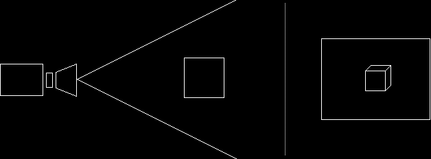
Field of View: 45 Degrees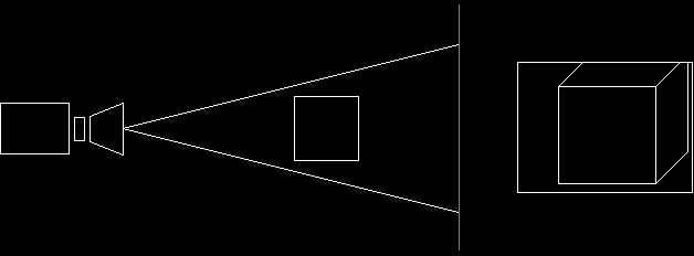
Field of View: 22.5 DegreesIn 3D graphics, the field of view is defined by setting the amount of radians allowed (vertically). The normal amount for this is 0.78539 (which is pi/4 radians, or 45 degrees)
Clipping is where Direct3D cuts out parts of an image that are unnecessary to draw. For example, if you have a large 3D environment which is too large to see the edge of (either because of fog or the horizon), then clipping can be used to cut out the parts of the image that are not going to be displayed anyway (the stuff that's beyond the fog).
Direct3D accomplishes this by asking for two view-planes. A view-plane is a set distance from the camera. Direct3D asks for two view-planes, and only draws the graphics that are shown in between. This is illustrated here.
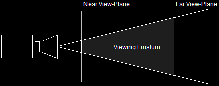
The Viewing Frustum
Setting up the Projection Matrix uses a function called D3DXMatrixPerspectiveFovLH(). It's quite a name, and its parameters are also numerous, although simple.
D3DXMATRIX* D3DXMatrixPerspectiveFovLH(D3DXMATRIX* pOut,
FLOAT fovy,
FLOAT Aspect,
FLOAT zn,
FLOAT zf);
This is the pointer to the matrix.
As discussed before, we need to set the field of view. This is typically set to 45 degrees (0.78539 radians). This can be changed depending on what amount of zoom you want in your game.
The aspect ratio is the ratio between the width of your screen and the height of your screen, in pixels. This is easy, because we have already defined them clearly (if you have come all the way through this tutorial). All you need to do is fill this value with:
(FLOAT)SCREEN_WIDTH / (FLOAT)SCREEN_HEIGHT. We convert each to a FLOAT in order to maintain accuracy in the division. Not doing this would make the result an integer, which will stretch the rendered image slightly.
This parameter defines the nearer view-plane. This should usually be set to 1.0, although later on we will find uses for other values. Putting it less that 1.0 will create a bug in the next lesson.
This parameter defines the farther view-plane. This should be set to the farthest distance you want your user to see, usually beyond the horizon, or where fog cuts everything out. We'll set it to 100.0 for now.
D3DXMATRIX matProjection; // the projection transform matrix
D3DXMatrixPerspectiveFovLH(&matProjection,
D3DXToRadian(45), // the horizontal field of view
(FLOAT)SCREEN_WIDTH / (FLOAT)SCREEN_HEIGHT, // aspect ratio
1.0f, // the near view-plane
100.0f); // the far view-plane
d3ddev->SetTransform(D3DTS_PROJECTION, &matProjection); // set the projection transform
With a bit of repetition and intellisense you should be able to master this function in no time.
Unfortunately, lighting must be mentioned in 3D. We don't have any code to add lights just yet, and without these, nothing will appear at all. Let's change that by turning off the lights just for now, and having everything show up normally (as if everything were lit automatically). To do this, we just have one command, which we may put in our initialization function initD3D().
d3ddev->SetRenderState(D3DRS_LIGHTING, FALSE); // turn off the 3D lighting
Fairly simple. This function is actually capable of quite a lot, and we'll go into some of the things it can do in the next few lessons.
Normally I would make a long table with all the options, but most of the concepts involved will be covered in later lessons, and this lesson is already long enough! We'll go over additional values when we come across a need for them.
Let's go over the entire pipeline one more time, and at the same time, let's look at how it plugs into your program as it exists. What I'll do is show you a completed render_frame() function as well as other parts of the program that should be changed slightly.
In the header, we need to change the vertex format. Before, we had pre-transformed vertices. Now our vertices are not transformed and so the vertex format is:
struct CUSTOMVERTEX {FLOAT X, Y, Z; DWORD COLOR;};
#define CUSTOMFVF (D3DFVF_XYZ | D3DFVF_DIFFUSE)
Next, in the initD3D() function, add the following command down at the bottom to turn off advanced lighting:
d3ddev->SetRenderState(D3DRS_LIGHTING, FALSE); // turn off the 3D lighting
Next, in the init_graphics() function, change the CUSTOMVERTEX array to this:
// create the vertices using the CUSTOMVERTEX struct
CUSTOMVERTEX t_vert[] =
{
{ 2.5f, -3.0f, 0.0f, D3DCOLOR_XRGB(0, 0, 255), },
{ 0.0f, 3.0f, 0.0f, D3DCOLOR_XRGB(0, 255, 0), },
{ -2.5f, -3.0f, 0.0f, D3DCOLOR_XRGB(255, 0, 0), },
};
Look closely to see what changed here. Not only do we change the numbers, but we also took out the RHW value that was previously there. We change the numbers to position the triange in front of our camera, which we will define next.
Now let's take a look at our new render_frame() function.
// this is the function used to render a single frame
void render_frame(void)
{
d3ddev->Clear(0, NULL, D3DCLEAR_TARGET, D3DCOLOR_XRGB(0, 0, 0), 1.0f, 0);
d3ddev->BeginScene();
// select which vertex format we are using
d3ddev->SetFVF(CUSTOMFVF);
// SET UP THE PIPELINE
D3DXMATRIX matRotateY; // a matrix to store the rotation information
static float index = 0.0f; index+=0.05f; // an ever-increasing float value
// build a matrix to rotate the model based on the increasing float value
D3DXMatrixRotationY(&matRotateY, index);
// tell Direct3D about our matrix
d3ddev->SetTransform(D3DTS_WORLD, &matRotateY);
D3DXMATRIX matView; // the view transform matrix
D3DXMatrixLookAtLH(&matView,
&D3DXVECTOR3 (0.0f, 0.0f, 10.0f), // the camera position
&D3DXVECTOR3 (0.0f, 0.0f, 0.0f), // the look-at position
&D3DXVECTOR3 (0.0f, 1.0f, 0.0f)); // the up direction
d3ddev->SetTransform(D3DTS_VIEW, &matView); // set the view transform to matView
D3DXMATRIX matProjection; // the projection transform matrix
D3DXMatrixPerspectiveFovLH(&matProjection,
D3DXToRadian(45), // the horizontal field of view
(FLOAT)SCREEN_WIDTH / (FLOAT)SCREEN_HEIGHT, // aspect ratio
1.0f, // the near view-plane
100.0f); // the far view-plane
d3ddev->SetTransform(D3DTS_PROJECTION, &matProjection); // set the projection
// select the vertex buffer to display
d3ddev->SetStreamSource(0, v_buffer, 0, sizeof(CUSTOMVERTEX));
// copy the vertex buffer to the back buffer
d3ddev->DrawPrimitive(D3DPT_TRIANGLELIST, 0, 1);
d3ddev->EndScene();
d3ddev->Present(NULL, NULL, NULL, NULL);
return;
}
Now that you see how it all fits in, let's go ahead and see the whole program for what it now is. The changed parts, as usual, are in bold.
[
Main.cpp]
// include the basic windows header files and the Direct3D header file
#include <windows.h>
#include <windowsx.h>
#include <d3d9.h>
#include <d3dx9.h>
// define the screen resolution
#define SCREEN_WIDTH 800
#define SCREEN_HEIGHT 600
// include the Direct3D Library files
#pragma comment (lib, "d3d9.lib")
#pragma comment (lib, "d3dx9.lib")
// global declarations
LPDIRECT3D9 d3d; // the pointer to our Direct3D interface
LPDIRECT3DDEVICE9 d3ddev; // the pointer to the device class
LPDIRECT3DVERTEXBUFFER9 v_buffer = NULL; // the pointer to the vertex buffer
// function prototypes
void initD3D(HWND hWnd); // sets up and initializes Direct3D
void render_frame(void); // renders a single frame
void cleanD3D(void); // closes Direct3D and releases memory
void init_graphics(void); // 3D declarations
struct CUSTOMVERTEX {FLOAT X, Y, Z; DWORD COLOR;};
#define CUSTOMFVF (D3DFVF_XYZ | D3DFVF_DIFFUSE)
// the WindowProc function prototype
LRESULT CALLBACK WindowProc(HWND hWnd, UINT message, WPARAM wParam, LPARAM lParam);
// the entry point for any Windows program
int WINAPI WinMain(HINSTANCE hInstance,
HINSTANCE hPrevInstance,
LPSTR lpCmdLine,
int nCmdShow)
{
HWND hWnd;
WNDCLASSEX wc;
ZeroMemory(&wc, sizeof(WNDCLASSEX));
wc.cbSize = sizeof(WNDCLASSEX);
wc.style = CS_HREDRAW | CS_VREDRAW;
wc.lpfnWndProc = WindowProc;
wc.hInstance = hInstance;
wc.hCursor = LoadCursor(NULL, IDC_ARROW);
wc.lpszClassName = L"WindowClass";
RegisterClassEx(&wc);
hWnd = CreateWindowEx(NULL, L"WindowClass", L"Our Direct3D Program",
WS_OVERLAPPEDWINDOW, 0, 0, SCREEN_WIDTH, SCREEN_HEIGHT,
NULL, NULL, hInstance, NULL);
ShowWindow(hWnd, nCmdShow);
// set up and initialize Direct3D
initD3D(hWnd);
// enter the main loop:
MSG msg;
while(TRUE)
{
while(PeekMessage(&msg, NULL, 0, 0, PM_REMOVE))
{
TranslateMessage(&msg);
DispatchMessage(&msg);
}
if(msg.message == WM_QUIT)
break;
render_frame();
}
// clean up DirectX and COM
cleanD3D();
return msg.wParam;
}
// this is the main message handler for the program
LRESULT CALLBACK WindowProc(HWND hWnd, UINT message, WPARAM wParam, LPARAM lParam)
{
switch(message)
{
case WM_DESTROY:
{
PostQuitMessage(0);
return 0;
} break;
}
return DefWindowProc (hWnd, message, wParam, lParam);
}
// this function initializes and prepares Direct3D for use
void initD3D(HWND hWnd)
{
d3d = Direct3DCreate9(D3D_SDK_VERSION);
D3DPRESENT_PARAMETERS d3dpp;
ZeroMemory(&d3dpp, sizeof(d3dpp));
d3dpp.Windowed = TRUE;
d3dpp.SwapEffect = D3DSWAPEFFECT_DISCARD;
d3dpp.hDeviceWindow = hWnd;
d3dpp.BackBufferFormat = D3DFMT_X8R8G8B8;
d3dpp.BackBufferWidth = SCREEN_WIDTH;
d3dpp.BackBufferHeight = SCREEN_HEIGHT;
// create a device class using this information and the info from the d3dpp stuct
d3d->CreateDevice(D3DADAPTER_DEFAULT,
D3DDEVTYPE_HAL,
hWnd,
D3DCREATE_SOFTWARE_VERTEXPROCESSING,
&d3dpp,
&d3ddev);
init_graphics(); // call the function to initialize the triangle
d3ddev->SetRenderState(D3DRS_LIGHTING, FALSE); // turn off the 3D lighting
}
// this is the function used to render a single frame
void render_frame(void)
{
d3ddev->Clear(0, NULL, D3DCLEAR_TARGET, D3DCOLOR_XRGB(0, 0, 0), 1.0f, 0);
d3ddev->BeginScene();
// select which vertex format we are using
d3ddev->SetFVF(CUSTOMFVF);
// SET UP THE PIPELINE
D3DXMATRIX matRotateY; // a matrix to store the rotation information
static float index = 0.0f; index+=0.05f; // an ever-increasing float value
// build a matrix to rotate the model based on the increasing float value
D3DXMatrixRotationY(&matRotateY, index);
// tell Direct3D about our matrix
d3ddev->SetTransform(D3DTS_WORLD, &matRotateY);
D3DXMATRIX matView; // the view transform matrix
D3DXMatrixLookAtLH(&matView,
&D3DXVECTOR3 (0.0f, 0.0f, 10.0f), // the camera position
&D3DXVECTOR3 (0.0f, 0.0f, 0.0f), // the look-at position
&D3DXVECTOR3 (0.0f, 1.0f, 0.0f)); // the up direction
d3ddev->SetTransform(D3DTS_VIEW, &matView); // set the view transform to matView
D3DXMATRIX matProjection; // the projection transform matrix
D3DXMatrixPerspectiveFovLH(&matProjection,
D3DXToRadian(45), // the horizontal field of view
(FLOAT)SCREEN_WIDTH / (FLOAT)SCREEN_HEIGHT, // aspect ratio
1.0f, // the near view-plane
100.0f); // the far view-plane
d3ddev->SetTransform(D3DTS_PROJECTION, &matProjection); // set the projection
// select the vertex buffer to display
d3ddev->SetStreamSource(0, v_buffer, 0, sizeof(CUSTOMVERTEX));
// copy the vertex buffer to the back buffer
d3ddev->DrawPrimitive(D3DPT_TRIANGLELIST, 0, 1);
d3ddev->EndScene();
d3ddev->Present(NULL, NULL, NULL, NULL);
}
// this is the function that cleans up Direct3D and COM
void cleanD3D(void)
{
v_buffer->Release(); // close and release the vertex buffer
d3ddev->Release(); // close and release the 3D device
d3d->Release(); // close and release Direct3D
}
// this is the function that puts the 3D models into video RAM
void init_graphics(void)
{
// create the vertices using the CUSTOMVERTEX struct
CUSTOMVERTEX vertices[] =
{
{ 3.0f, -3.0f, 0.0f, D3DCOLOR_XRGB(0, 0, 255), },
{ 0.0f, 3.0f, 0.0f, D3DCOLOR_XRGB(0, 255, 0), },
{ -3.0f, -3.0f, 0.0f, D3DCOLOR_XRGB(255, 0, 0), },
};
// create a vertex buffer interface called v_buffer
d3ddev->CreateVertexBuffer(3*sizeof(CUSTOMVERTEX),
0,
CUSTOMFVF,
D3DPOOL_MANAGED,
&v_buffer,
NULL);
VOID* pVoid; // a void pointer
// lock v_buffer and load the vertices into it
v_buffer->Lock(0, 0, (void**)&pVoid, 0);
memcpy(pVoid, vertices, sizeof(vertices));
v_buffer->Unlock();
}
If you run this program, you will find a triangle similar to the one in the last lesson, only this time it is rotating as well!

The Rotating Triangle Now you know enough for at least some innovation! We've covered how to do just about anything with a virtual camera, and with 3D objects. Try changing this code around to get the feel of it, then I'd recommend doing these exercises:
1. Make the triangle rotate in the other direction.
2. As the triangle rotates, make it lift off like a rocket (but have the camera stay pointed at the triangle).
3. Extend the far view-plane so that the rocket does not disappear.
4. Now make the triangle lie flat while it rotates (be careful, it can only be seen from one side).
5. Make the triangle rotate instead along the z-axis.
6. Make the position of the camera change.
7. Now set it up to zoom in and zoom out!
8. Use SetRenderState() to draw both sides of the triangle.
And when you're done, I've got something important to tell you in the next lesson, so don't quit just yet!
Next Lesson: Rendering Depth
GO! GO! GO!
© 2006-2026 DirectXTutorial.com. All Rights Reserved.
Expand