First of all, I officially welcome you to Direct3D. I would like to teach you both the basics and the advanced topics of 3D programming. Whether you want to build your own engine, borrow one and modify it, or just buy one and use it, it is important that you understand the concepts underlying it.
Just as important as the underlying concepts of a game engine are the concepts underlying Direct3D itself. This lesson will cover the basics of Direct3D and what you need to know for you to punch out your first Direct3D program.
This first lesson is a theoretical lesson. We will cover the practice involved in the next lesson.
A good understanding of graphics programming requires a good understanding of the hardware involved with graphics. Direct3D is not so much a game platform as it is a hardware interface. Everything you do in Direct3D is done in order to manipulate the graphics hardware itself. Without an understanding of the graphics hardware, Direct3D is nearly useless.
The piece of hardware that we are primarily interested in with graphics programming is the GPU, or graphics processing unit. This is differs from the CPU (central processing unit) in some structural ways, but primarily in what it is used for. The CPU performs calculations and directs the entire computer. The GPU performs calculations on graphics and directs graphics output to the monitor.
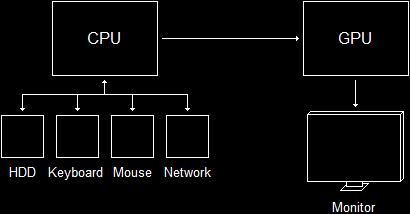
The CPU Directs the GPUIn addition to having its own separate processor, graphics programming works with a completely isolated portion of memory called the video memory. It is actually physically separate. Instead of existing on the motherboard, video memory typically exists on the video card, so it can be quickly accessed by the GPU. The video memory is used to store the current image on the screen, as well as any data that might be used to compile the next image.
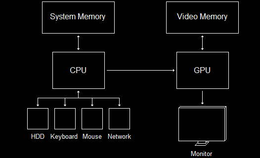
The CPU and GPU Have Separate MemoryAs far as physical hardware goes, that's really all we need to worry about. Direct3D will, for the most part, manage when data is stored in system memory or video memory, and you don't need to worry about it.
The DirectX Graphics Infrastructure is a component that lies at the base of all the most recent versions of Direct3D. Its job is to handle fundamental tasks such as displaying images on the screen and finding out what resolutions the monitor and video card can handle.
DXGI is not actually a part of Direct3D. It underlies it and other graphics components, and it acts as an interface between Direct3D and the hardware.
DirectX Graphics InfrastructureThere are ways to deal with DXGI directly, but we will not get into these. All that's important is that you are aware this component exists, as there are parts of Direct3D which exclusively deal with DXGI.
A GPU contains in its memory a pointer to a buffer of pixels that contains the image currently being displayed on the screen. When you need to render something, such as a 3D model or image, the GPU updates this array and sends the information to the monitor to display. The monitor then redraws the screen from top to bottom, replacing the old image with the new.
However, there is a slight problem with this in that the monitor does not refresh as fast as needed for real-time rendering. Most refresh rates range from 60 Hz (60 fps) to about 100 Hz. If another model were rendered to the GPU while the monitor was refreshing, the image displayed would be cut in two, the top portion containing the old image and the bottom portion containing the new. This effect is called tearing.
To avoid this, DXGI implements a feature called swapping.
Instead of rendering new images directly to the monitor, DXGI draws your images onto a secondary buffer of pixels, called the back buffer. The front buffer would be the buffer currently being displayed. You draw all your images onto the back buffer, and when you are done, DXGI will update the front buffer with the contents of the back buffer, discarding the old image.
However, doing this can still cause tearing, because the image transfer can still occur while the monitor is refreshing (the GPU is way faster than the monitor).
In order to avoid this (and to make the whole thing go faster anyway), DXGI uses a pointer for each buffer (both front and back) and simply switches their values. The back buffer then becomes the front buffer (and vice versa), and no tearing occurs.
Addresses Swap InstantlyOf course, we could make our game have better performance by adding additional back buffers, like this.
Multiple Back Buffers Can Get Better PeformanceThis setup is called the swap chain, as it is a chain of buffers, swapping positions each time a new frame is rendered.
If there is one thing you will hear about a lot in graphics programming, it is the rendering pipeline. This is because the rendering pipeline is where everything happens.
The rendering pipeline is the process which produces a rendered 3D image on the screen. It works like an assembly-line, one step after another. It consists of steps which are executed on the GPU.
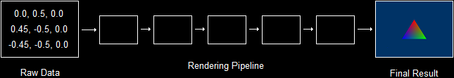
The Rendering PipelineWe won't cover all of the steps here, but we'll cover a few. We'll need to understand these steps in order to get started, then we can explore the rest as we go along.
The Input-Assembler Stage is the first step in the pipeline. It's responsibility is to "chew the food" so to speak. It collects information from video memory about the 3D models you wish to render. It then compiles the information and prepares it for rendering.
The Rasterizer Stage is responsible for determining where on the back buffer images are to be drawn, or more specifically, which exact pixels will be drawn and what color they will be.
The Output-Merger Stage is the final step in the pipeline. It's job is to combine the individual model images into one whole image, and to place that image correctly on the back buffer.
Without understanding of the basic math of 3D, 3D programming would be impossible. And I don't mean doing college algebra all over again, but just understanding the concepts of 3D coordinates, how they work and the various things which might get in your way.
In 3D rendering, there are several types of coordinates we should know. The first one you may have heard of. They are called Cartesian Coordinates.
The Cartesian Coordinate System might be better recognized if called a 2D coordinate system. In other words, it is a system of locating an exact point on a flat surface.
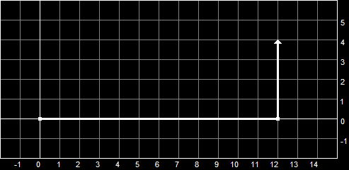
A point is defined as an exact position along an axis. If we wanted to know how far something has gone, we usually give an exact number, as in "Bob walked 12 meters". 12 meters is a distance along a single axis. We say that 0 is our starting point, and as Bob progresses, he moves farther and farther along this axis. This is a 1D coordinate system.
1D Coordinate SystemWhen we look at this scenario from the side, as in the picture, we can see that as Bob continues walking toward the right of the screen, his distance travelled increases away from 0. We will call this '0' the origin, as it is where he started from. On the other side of the origin, we would have negative values instead of positive values.
However, what if he were then to turn 90 degrees and walk in a different direction? Truthfully, Bob would then be walking along a second axis, and we would diagram his path like this:
The Cartesian Coordinate SystemNow that we have more than one axis, we give ourselves a way to identify them. The horizontal axis, along which Bob walked 12 meters, we will call the x-axis. The vertical axis we will call the y-axis.
Of course, this new axis, like the horizontal axis, also has an origin. It is the point where Bob stopped walking sideways and started walking up. Notice that the y-axis origin is also given the value of 0, and increases the farther Bob walks. (go Bob go...)
So now we have two axes (the x-axis and the y-axis), and each have their origins. Well, this is what forms our Cartesian Coordinate System. We can now locate any point along this surface (probably the ground in Bob's case). We can state Bob's exact position by saying how far he is off of each axis' origin, so we could say he is at (x, y) or (12, 4), 12 being his position on the x-axis and 4 being his position on the y-axis.
These two numbers are called coordinates, and are used to show how far an exact point is from the origin (or the '0' point on both axes).
Actually, the 3D Coordinate System is merely an extention to what we have been discussing. If we took Cartesian Coordinates and added a third axis (a z-axis) running perpendicular to both the x and y axes, we would have 3D coordinates. This is illustrated here.
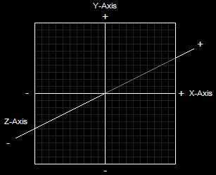
The 3D Coordinate SystemLike Cartesian Coordinates, 3D coordinates can be both positive and negative, depending on which direction the point is. However, instead of being written like Cartesian Coordinates, 3D coordinates are written with three numbers, like this: (x, y, z) or (12, 4, 15). This would indicate that Bob was somehow fifteen meters in the air. It could also be written (12, 4, -15). Perhaps this means he's lost in a dungeon somewhere.
Now let's cover how 3D coordinates are applied to games and game programming. If a point in a 3D coordinate system represents a position in space, then we can form an array of exact positions which will eventually become a 3D model. Of course, setting so many points would take up a lot of space in memory, so an easier and faster way has been employed. This method is set up using triangles.
Triangles, of course, are a very useful shape in just about any mathematical area. They can be formed to measure circles, they can be used to strengthen buildings, and they can be used to create 3D images. The reason we would want to use triangles is because triangles can be positioned to form just about any shape imaginable, as shown in these images:
Models Made From TrianglesBecause of the useful nature of triangles when creating 3D models, Direct3D is designed solely around triangles and combining triangles to make shapes. To build a triangle, we use something called vertices.
Vertices is plural for vertex. A vertex is defined as an exact point in 3D space. It is defined by three values, x, y and z. In Direct3D, we add to that a little. We also include various properties of this point. And so we extend the definition to mean "the location and properties of an exact point in 3D space".
A triangle is made up of three vertices, each defined in your program in clockwise order. When coded, these three vertices form a flat surface, which can then be rotated, textured, positioned and modified as needed.
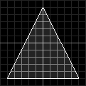
A Triangle Built From VerticesThe triangle shown in this diagram is created by three points:
x = 0, y = 5, z = 1
x = 5, y = -5, z = 1
x = -5, y = -5, z = 1
You will notice that all the above vertices have a z-value of 1. This is because we aren't talking about a 3D object; we are talking about a triangle, which is a 2D object. We could change the z-values, but it would make no essential difference.
To make actual 3D objects, we will need to combine triangles. To take a simple example, the cube is simply two triangles placed together to create one side. Each side is made up of identical triangles combined the same way.
However, defining the 3D coordinates of every triangle in your game multiple times is more than just tedious. It's ridiculously complex! There's just no need to get that involved (and you'll see what I mean in the next lesson).
Instead of defining each and every corner of every triangle in the game, all you need to do is create a list of vertices, which contain the coordinates and information of each vertex, as well as what order they go in.
A primitive is a single element in a 3D environment, be it a triangle, a line, a dot, or whatever. Following is a list of ways primitives can be combined to create 3D objects.
1. Point Lists
2. Line Lists
3. Line Strips
4. Triangle Lists
5. Triangle Strips
A Point List is a list of vertices that are shown as individual points on the screen. These can be useful for rendering 3D starfields, creating dotted lines, displaying locations on minimaps and so on. This diagram shows how a Point List is shown on the screen (without the labels, of course).
A Point List (6 Primitives)A Line List is a list of vertices that create separate line segments between each odd-numbered vertex and the next vertex. These can be used for a variety of effects, including 3D grids, heavy rain, waypoint lines, and so on. This diagram illustrates how a Line List is shown on the screen (this is the same set of vertices as before).
A Line List (3 Primitives)A Line Strip is similar to a line list, but differs in that all vertices in such a list are connected by line segments. This is useful for creating many wire-frame images such as wire-frame terrain, blades of grass, and other non-model-based objects. It is mostly useful in debugging programs. This diagram illustrates how a Line Strip is shown on the screen.
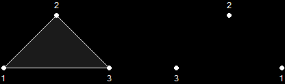
A Line Strip (5 Primitives)A Triangle List is a list of vertices where every group of three vertices is used to make a single, separate triangle. This can be used in a variety of effects, such as force-fields, explosions, objects being pieced together, etc. This diagram shows how a Triangle List is shown on the screen.
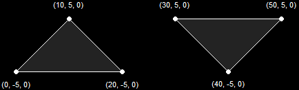
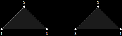
A Triangle List (2 Primitives)A Triangle Strip is a list of vertices that creates a series of triangles connected to one another. This is the most-used method when dealing with 3D graphics. These are mostly used to create the 3D models for your game. This diagram illustrates how a Triangle Strip is shown on the screen. Notice that the first three vertices create a single triangle, and each vertex thereafter creates an additional triangle based on the previous two.
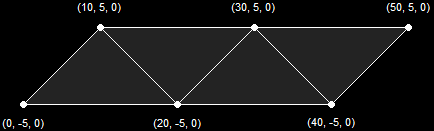
A Triangle Strip (4 Primitives)There is a slight quirk in drawing primitives where only one side of the primitive is shown. It is possible to show both sides, but usually a model is completely enclosed, and you cannot see the inside of it. If the model is completely enclosed, only one side of each triangle need be drawn. After all, drawing both sides of a primitive would take twice as much time. You will see an example of this in the next couple of lessons.
A triangle primitive is only drawn when its vertices are given in a clockwise order. If you flip it around, it becomes counter-clockwise, and is therefore not shown.
Primitive Only Visible When Drawn ClockwiseThere is an easy way (though tedious when you get into larger games) to show both sides of a primitive, which is to show the primitive twice, giving one primitive clockwise and the other counter-clockwise.
Primitive Visible When Drawn Either Way Graphics programming is a simple subject, provided you have a good understanding of the basics. If you are still having trouble with these concepts, don't worry too much. You'll be able to see how they're important in the next lesson, and you can always come back and read this again.
So let's go ahead and start! We have quite an adventure ahead of us!
Next Lesson: Initializing Direct3D
GO! GO! GO!
© 2006-2026 DirectXTutorial.com. All Rights Reserved.
Expand